 I finally got my hands on an HF transceiver last week. It’s a gently used IC-735, with CW, SSB, AM, and FM on all bands 160-10 meters with the exception of 60 meters. It has had the MARS modification done on it, so it will transmit on any frequency between 100 kHz to 30 MHz. It has a max power output of 100 watts in CW, SSB, and FM modes, and 40 watts in AM. A handy rig to have for a ham who’s just starting out. It’s certainly not as spiffy as the brand new DSP rigs with huge LCD displays and power computers under the hood, but there are more than enough features to satisfy the beginning to intermediate operator. Since I got the rig on the air on March 10th, I’ve had six contacts with my straight key, each in a different state, so I only need 44 more states to get WAS!
But I’m getting ahead of myself. The fanciest, most expensive rig on the planet isn’t worth a hill of beans without an antenna to send and receive signals. I’ve avoided HF for a long time because I assumed the antenna requirements would be too costly in terms of space and money. I live in a townhouse with no attic, no basement, and a postage stamp yard, and putting up antennas outside is entirely out of the question. There simply isn’t enough space to string up a full sized dipole indoors for most of the HF bands. I had the inspiration, however, to try setting up an antenna for 20 meters, which is a popular HF band and should also resonate on 10 meters if designed carefully.
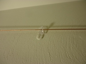
You can see the design here. It’s a semi-square with a 12.6′ base leg and two 9.6′ legs at 90 degrees. At my shack the base leg runs east to west, and the two shorter legs run north to south. It hangs 7.25′ above ground level around the ceiling, suspended with no-damage .5 lb plastic hooks attached to the wall. Obviously this isn’t a very ideal setup, but the results speak for themselves I think. Sure, other setups will have less noise and a lower takeoff angle, but I’ve had signal reports of 579 and above from as far away as California. With a tuner, I’ve been able to load it up on all bands between 80 and 18 MHz with full power and an SWR no higher than 1.3:1. Your mileage may vary, and with indoor antennas a lot of things must be taken into account such as wiring inside the walls, what material the walls and exterior of your building are made of, how many floors are above and below you, and most importantly of all, especially in an apartment situation you must take the RF exposure into account for both yourself and your neighbors. With all of these factors in mind, however, there’s no reason any ham with a room at least 12’x16′ can’t put up a modest antenna to at least get started on their WAS certificate.
 The radiation pattern is pretty close to omni-directional, which is what I was shooting for in my setup. This increases the noise level somewhat, but allows for contacting stations at all points of the compass, any time of day, without having to rotate the antenna. In point of fact, however, because the antenna isn’t secured to anything permanently the feedpoint can be shifted left and right to adjacent hangers to provide some slight directivity in the direction of the leg that gets shortened in this process. In this scenario, however, any gain this antenna might provide is pretty much lost, so I wouldn’t recommend trying this unless you want to experiment.
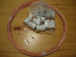
I used very inexpensive and easy to find materials to put the antenna together. The antenna itself is made of #14 7-strand copper-clad steel available currently at 24 cents a foot. I bought 100′ since the price drops to 19 cents per foot and you can never have too much antenna wire laying around. The kit of 16 clear no-damage 1/2lb hooks cost $6 from the hardware store. I also got a bag of ten 1/2″ PVC couplings to act as standoffs and supports where needed. This bag cost $2. For the feedline I used a standard 6′ RG 8/U coax line I bought from Radio Shack a while back for around $6. I had to cut one of the ends off and strip it for the feedpoint itself, but the other end has an PL-239 on it conveniently. Altogether I spent around $20 for the entire antenna, not counting tools I had laying around already. If you don’t have any tools, at the very least you will need a wire cutter and stripper, and preferably a set of pliers, a drill and bits, and some electrical tape.
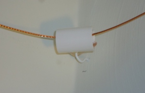
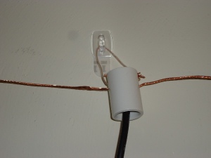
 Once you have all the parts, antenna construction is pretty simple. I measured and marked spots every two to three feet and hung up the no-damage hooks. I had a problem at first at the corners because I ran the wire directly through the hooks. There was too much strain and after about 20 minutes the hooks came flying off the walls with the wire. Not a safe situation so be careful of this. I solved this issue by using one of the PVC couplers at each corner, and using a short bit of wire or string looped through the coupler and over a sturdier hook that actually screws into the wall. This supports the wire away from the wall and relieves some of the strain on the hook. I used a similar technique to hang the feedpoint and center of the dipole. The coax goes up through the middle of the coupler and is split at the top. The two antenna wires enter the coupler through holes drilled in the sides, then go up and over the top where they meet with the shield and center conductor of the coax. Two more sets of holes provide tie points for a short bit of wire from which the hole assembly hangs. This means the centerpoint can be moved back and forth between the different hooks as mentioned before, very easily.
 I haven’t contacted any juicy DX with this antenna yet, but considering how inexpensive it was, and that it only took me about two hours to put it up, I’m more than satisfied with the performance so far. I’ve gotten great signal reports and have had no trouble making at least one or two contacts every night, without trying very hard. I’m sure there are many improvements that could be made to this design, and I encourage everyone to experiment with it and share your results with me. However, if you’re short on cash after dumping your allowance on a rig, this design should provide plenty of inspiration to anyone who thinks they can’t put up an antenna.


Hi: I’d like to try this. Does it matter if the base leg is a bit shorter as long as the total length is the same? Thanks, Pete Curry, KA2TTU
Hi Pete,
As far as I can tell the only difference a shorter base leg might make is in making it a bit more directional. As it is setup at my house it’s already much more sensitive along an axis perpendicular to the base leg and in the opposite direction of the two side legs. So for instance the opening of the “C” shape points south and I get much more reception from the north than from any other direction, but I have still made contacts in all other directions as far as 1,000 miles or so. If you get your put up please send me some pictures and let me know how it works!
–73 de Josh NC4JB
Thanks, Josh. I’ll let you know how I make out, Pete
Hi Again: In your headline you talk about 80m to 15m coverage with this antenna–with “m“ I assume meaning meters. But in the third paragraph you say you can load it up on all bands between “80 and 18 MHz.” If these numbers are both MHz, shouldn’t the first one be something like 3.5 to 4.0? Thanks, Pete/KA2TTU
Hi Pete, Sorry it took me 4 years to see this! You are correct that is a type and I meant to say 80-17 meters (3-18 MHz). 73s.
May this blog post be an example to all those folks out there troubled by a home owners association or landlord. With a CW key and a curious experimenter attitude you can doit.
(which should be the definition of a radio amateur)
Too bad all measurement units here limit the use of this post to the imperial colonies.
But that should not hold anyone back as you can manage with a unit-converter of some sorts.
hello bro!no antenna tuner for use it please
I have read with great interest your (old) post. Do you have updates, experiences, and hints to share? Are you still using such an indoor dipole? Your post sparkled great interest to me.
Hello Michele! Sorry for the late reply.
I moved away from that QTH six years ago and am no longer using that dipole, but from what I have learned since I can tell you it suffered enormously from common mode currents at anything above 10W or so. I believe a better physical and electrical connection from the coax to the dipole legs along with a balun would have resolved most of this. That being said, I was able to make a handful of regional contacts with the antenna as described in the post before life took me away from ham radio for a while. Given the hastiness and quality of construction and lack of balun and proper grounds I’m amazed that it functioned as well as it did.
It is interesting that few people never look for the benefits on indoor antennas, one ways of escaping the negative effects.
Yes, an indoor antennas is less efficient and a compromise, but sitting close to the feed point allows you to place an ATU at the feed point itself. This is not possible with a big dipole up a tree in the garden.
This antenna design can also features trimmed in seconds by rolling up the ends, then unrolling when you change bands.
I live in apartment with a metal roof balcony, but neigh ours have not noticed two extra plastic drainpipes fixed to the apartment block outside wall. The side lengths of my antenna are outside and hang vertically. I can pull up wire, coil and short to trim, all without the neighbours seeing anything.
BRING Harry – SM0VPO
sm0vpo.forumstopic.com
Soooooooo. Any updates to this design because i just realized that I have everything I need to do this so here we go.
Hi Harold!
I would very strongly recommend incorporating a balun at the feedpoint and finding some way to ground the coax shield at the antenna tuner. This will reduce or eliminate common mode currents that the original design suffered from enormously and improve the antenna’s ability to “get out”. You could also experiment with making the legs even longer.
I’d like to give this a shot! What can I do to make it safe so as to minimize RF exposures.
Reblogged this on Site Title.
Hi! A couple of questions: 1) Can it handle 500W CW, and if not, how would u modify it for higher power? 2) What make and model of tuner are you using with it? Thank you!
I don’t think it would very wise to run 500 watts to an antenna that is only a few feet from your head. Also you might run the wire down and around your windows so you can get more wire up and cut it for a lower band. 73 AA4TG
Take a look at shortening the space required for the antenna wire using the Sabertooth Wire method. It will show up in a network search.
Can you show a closeup of how the center connection is made.
Hi George!
I took this antenna down several years ago so I can no longer take pictures of it, but I can tell you that it was a pretty barbaric connection. I stripped the end of the coax and soldered one leg to the center conductor and the other leg to the coax shield. Later on I experimented with using 450-ohm window line for the feedline but noticed no difference in performance. As mentioned in other comments I would very strongly suggest using a balun between the coax and the dipole legs to reduce common mode currents.
Thanks for pointing this to me on FB post. I will try my best to emulate your design and post pics of it. Wish me good luck!
Great article and genius idea! Could you diagram the feed point connections for us novices? Thanks! aamp54@yahoo.com
So is the main leg 12′ 6 ” Long or is is it 25′ long with the feed point at 12′ 6″. Thanks
Joe K4XZ